Computer Engineering · Florida Polytechnic University
Ethan Beasley
I build hardware that does something you can watch: digital logic on a breadboard, CPUs designed from the gate level up, and small robots that steer themselves or follow commands from a smartwatch.
B.S. Computer Engineering · Dec 2026
Robotics Intern · SOFWERX
Systems Engineer · Tampa Microwave
Riverview, FL
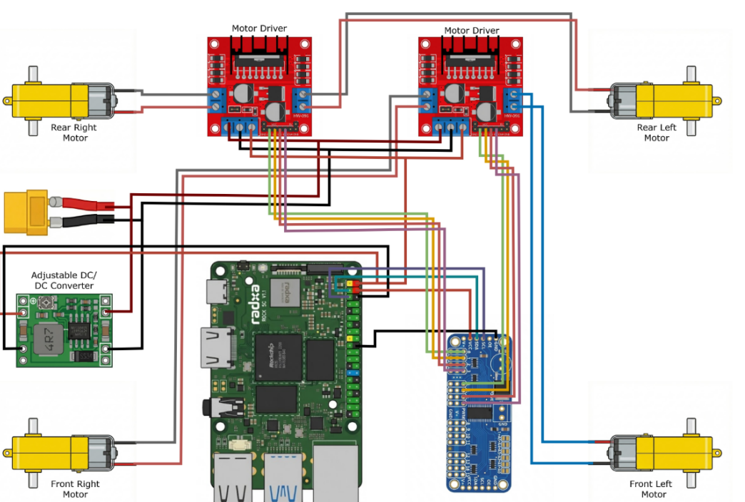
Car completing laps of the track on its ownWiring: compute board, PWM bridge, motor drivers and power
01 Robotics · Computer vision
Autonomous Vision-Guided Car
A four-wheel robot car that drives a taped track with no remote control. A camera on the car reads the lane markings, and a Radxa ROCK 5C turns each frame into steering decisions in real time, sending motor commands through an I²C PWM board to two motor drivers.
Focus
Camera-based lane following, closed-loop steering
Compute
Radxa ROCK 5C single-board computer
Drive
Four DC gear motors on two H-bridge motor drivers, commanded through a PWM board over I²C
Power
Battery through an XT60 lead, DC-DC converter set to 5.2 V for the computer
Result
Continuous laps of the track without intervention
Driving the car from the watch on my wrist
02 Embedded · Wireless control
Smartwatch-Controlled Car
A robot car driven entirely from a smartwatch. Commands from the watch are sent wirelessly to the car's controller, which translates them into motor output, so the car responds to the wearer without a handheld remote.
Focus
Wearable interface, wireless link, motor control
Platform
Four-wheel robot car and a smartwatch
Result
Live driving demo on the floor
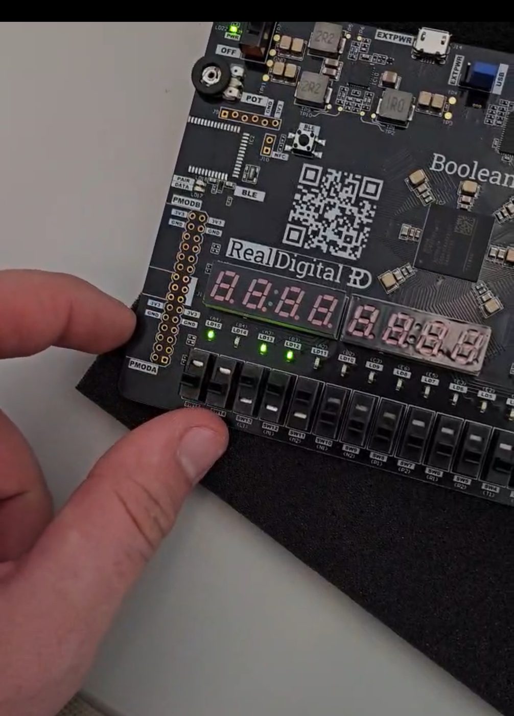
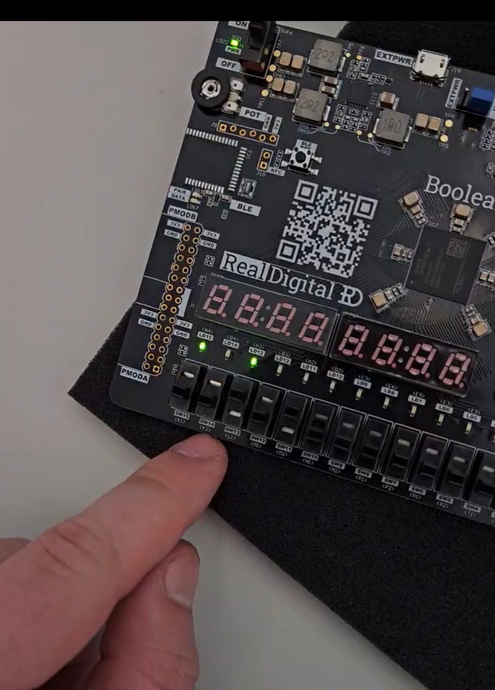
One term of the sequenceA step later
03 Digital design · FPGA
CPU on an FPGA
A processor designed and implemented on an FPGA. To prove it works, the CPU runs a program that computes the Fibonacci sequence and shows each term on the board's LEDs as it executes.
Focus
Datapath, control unit, instruction execution
Platform
Real Digital Boolean FPGA board
Result
Fibonacci program running on custom hardware
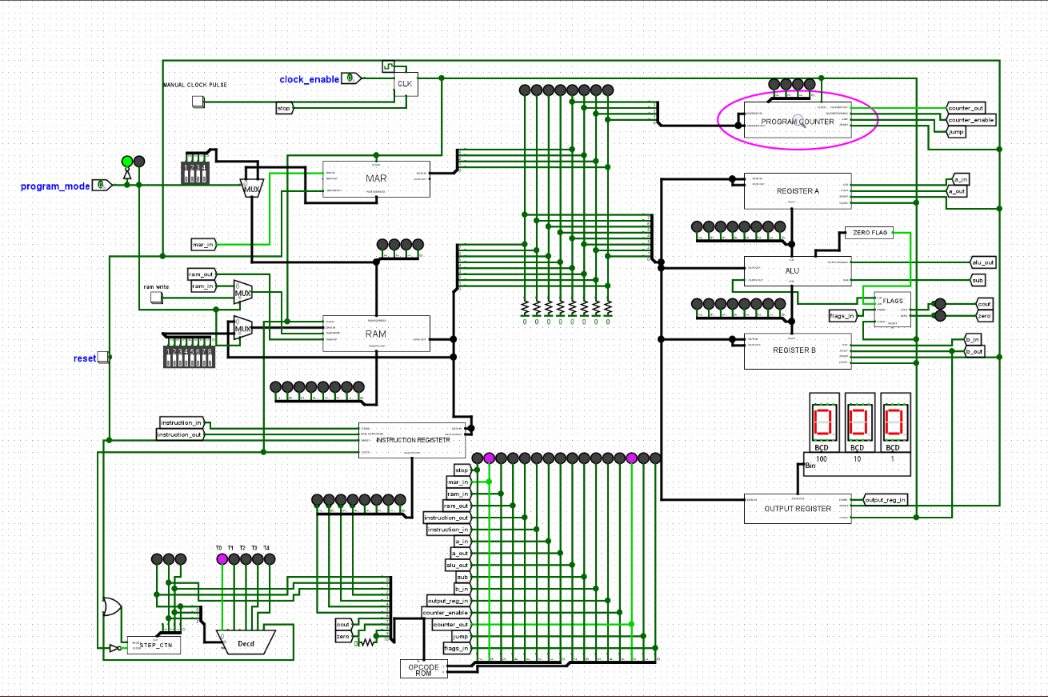
Full CPU schematic in Logisim
04 Computer architecture · Simulation
8-Bit Microcoded CPU in Logisim
An 8-bit processor built gate by gate in Logisim. A program counter, memory address register, RAM, instruction register, registers A and B, an ALU and an output register all share one bus. A step counter and an opcode ROM generate the control signals for each instruction, one micro-step at a time. Program mode and a manual clock let me enter code into RAM by hand and single-step through it.
Focus
Datapath and control design, microcoded instruction sequencing
Datapath
PC, MAR, RAM, instruction register, registers A and B, ALU with add and subtract, output register on BCD displays
Control
Step counter (T0–T4), opcode ROM, carry and zero flags for conditional jumps
Tool
Logisim
Tag scanned, gate arm lifts
05 Embedded · RFID
RFID Toll Gate
A working model of an electronic toll lane. When a "vehicle" carrying an RFID tag reaches the reader, the microcontroller reads the tag and drives a servo that raises the gate arm, then lowers it again.
Focus
RFID reading, servo actuation
Hardware
Microcontroller, RFID reader and key fob tags, servo
Result
Gate opens on a scanned tag
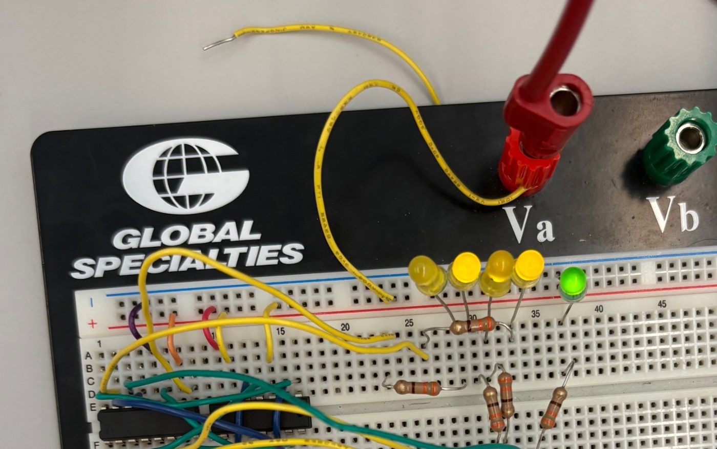
Four yellow LEDs for the sum, green for carry out
06 Digital logic · Breadboard
4-Bit Binary Adder
Two 4-bit numbers added in hardware. The circuit is wired by hand on a breadboard, with the result shown in binary on four LEDs and a fifth LED lit when the sum overflows into a carry.
Focus
Combinational logic, binary addition, carry
Hardware
Logic IC, resistors, LEDs, bench supply
Output
S3–S0 plus Cout
Contact
Graduating December 2026 and looking for electrical, systems and robotics roles.